01
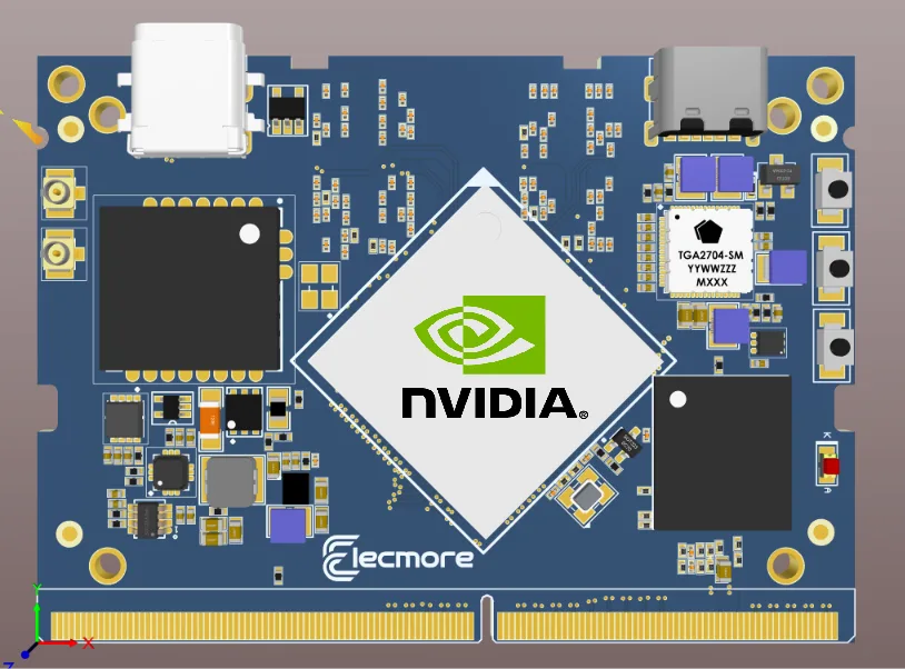
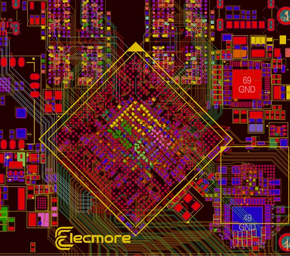
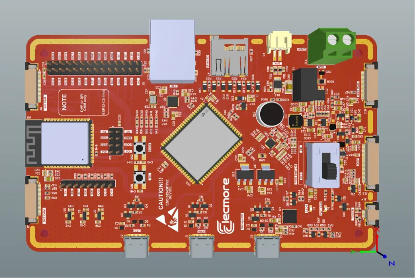
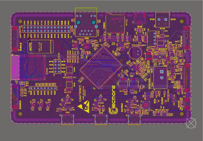
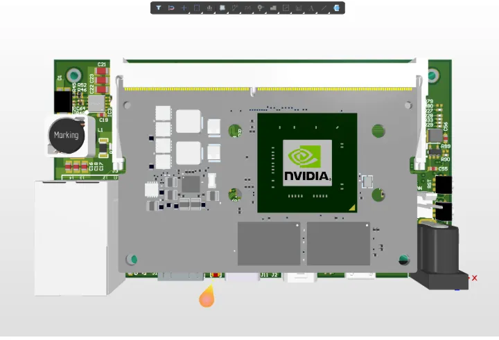
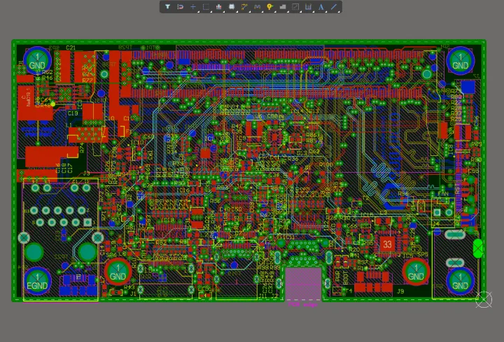
12-layer NVIDIA Jetson SoM motherboard
Custom carrier and system board for an edge-AI product: high-speed SoM interfaces, power tree, and dense HDI routing across 12 layers.
Length-matched high-speed groups passed SI simulation before fab.
High-speed digital, power, RF and edge-AI hardware — simulated before fabrication, supported through bring-up.
30 min · scope and fixed quote on the call · 4.8★ on Clutch
9+ years
Shipping hardware
UK Ltd
Companies House #15835884
Reviewed
On Clutch and DesignRush
Altium · KiCad
Cadence-compatible deliverables
Selected work
Hover a board for the X-ray
More work available under NDA. Ask on the call.
Services
Idea to production. Architecture, schematic, layout, simulation, prototype bring-up, and production files. One accountable engineer end to end.
Send your schematic, get routed boards. DDR4/5, PCIe, GDDR6, USB3, Ethernet, with impedance control and length matching documented.
Pre-fab design review with signal integrity, power integrity, and EMI/EMC simulation. Find respins before the fab does.
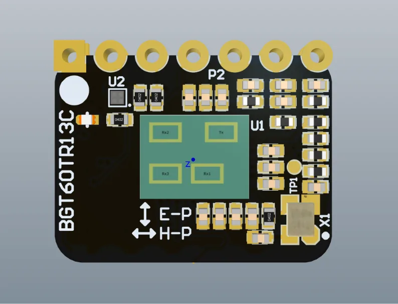
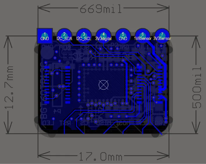
60 GHz radar, antenna integration, RF front ends, and the grounding discipline that makes them work.
Beyond PCB design
We already cover the whole product around the board, from the first requirement to production support. One accountable team across every discipline below, so nothing falls between suppliers.
36capabilities
across 7 disciplines
An idea turned into a buildable, costed specification.
3 capabilitiesCircuits and boards, from schematic to routed layout.
5 capabilitiesThe physics that decides whether it works first time.
7 capabilitiesThe code that brings the hardware to life.
6 capabilitiesThe enclosure and everything the board has to fit.
2 capabilitiesFirst units built, brought up and proven.
7 capabilitiesReady for volume, with the supply chain behind it.
6 capabilitiesNeed one discipline or all of them, the first call is the same: scope, risks and a fixed quote.
Complete product development
Elecmore can support the complete development of an electronic product, from early requirements and system architecture to electronics, firmware, mechanical design, prototypes, testing and manufacturing.
For technically demanding products, the same team can also handle high-speed PCB design, DDR4/5, PCIe, RF, signal integrity and power integrity.
Stage 01 / 08
Define what the product must do.
Use cases, constraints, cost targets and compliance goals, checked for feasibility before any design starts.
How the work runs
Three phases, one accountable engineer. Nothing is handed to a fab until it has been simulated and reviewed by a human.
| DESIGN | REVIEW | MANUFACTURE |
|---|---|---|
|
SCHEMATIC & LAYOUT: architecture, part selection, schematic capture and impedance-controlled routing, from 2 to 12+ layers. STACKUP FIRST: layer stack, impedance targets and BGA fanout are settled before a single track is routed. EDA NATIVE: we work in your Altium or KiCad workspace, templates and libraries, or set them up for you. Cadence-compatible deliverables on request. |
SIMULATE BEFORE COPPER: signal integrity, power integrity and thermal analysis run before fabrication, not after the first spin fails. HUMAN REVIEW: every schematic is peer-reviewed and annotated by an experienced engineer before it moves to layout. EMC PRE-SCAN: EMI and EMC risks are found on the bench-top model, with a written pre-compliance checklist you keep. |
FULL FAB PACKAGE: Gerbers, BOM, pick and place and assembly drawings, plus the native source files. You own all of it. FAB COORDINATED: trusted fabs and assembly houses, their DFM feedback handled by us, everything billed at cost with invoices shared. BRING-UP: board on the bench, measured and firmware-ready, backed by a 12-month design warranty. |
Edge AI hardware
We design carriers and full systems for modern AI silicon: NVIDIA Jetson, Rockchip RK3588 and RK3399, NXP i.MX 8M Plus, AMD Xilinx Zynq and Versal, and GDDR6 memory subsystems. Power delivery, memory routing, and thermal design are handled as one problem, because on these boards they are one problem.
ELECMORE
DS-4CH
RUNMulti-rail PDN designed and simulated for NPU transient loads.
DDR4/5 and GDDR6 routed to spec with fly-by and point-to-point topologies.
Copper pours, via farms, and heatsink strategy simulated before you buy tooling.
Evidence, not promises
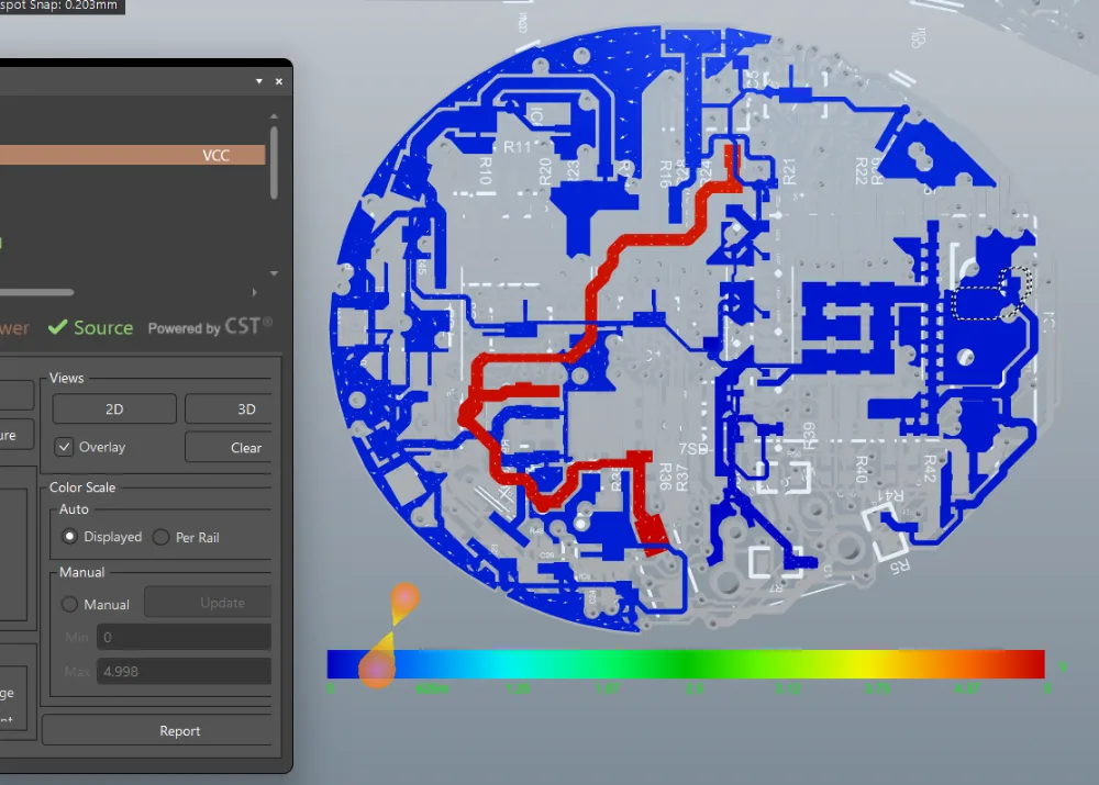
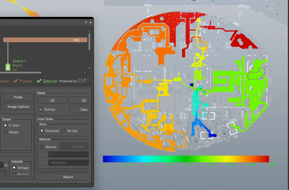
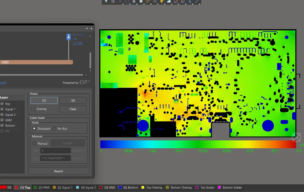
Every power rail is solved for DC drop and current density before a single board is ordered. These are real captures from a recent build: the PDN analysis, the thermal and current-density check, and the board those simulations produced.
Simulation reports ship with every project.
Rugged by design
For industrial, outdoor, and vehicle-mounted products we design to extended temperature ranges, derate every component, plan conformal coating and mechanical strain relief, and document the reliability decisions.
Enhanced Lifetime & Reliability Analysis
A component-by-component assessment of your board against how it will really be used. You learn what limits its service life and what to change, before you commit to a long warranty.
Sample certificate
Elecmore Ltd · Reliability Engineering
Certificate
of Enhanced Lifetime & Reliability Analysis
This certifies that the printed circuit assembly named below has completed a component-by-component lifetime and reliability assessment against its stated operating profile.
Where long PCB life matters
For space, defence and critical infrastructure, service life is a requirement, not a bonus. It has to be designed in, part by part, and proven before the first unit ships.
There is no repair once it launches. Thermal cycling in orbit and vacuum shape every material and solder-joint choice.
Missions of 15+ yearsPlatforms stay in service for decades, through shock, vibration and wide temperature swings, and outlive the parts they were built with.
Service lives of 20–30 yearsConstant thermal cycles between ground and altitude, plus vibration, and every failure is costly to diagnose and recertify.
Airframes flying 20+ yearsInverters, substations and smart meters run 24/7 outdoors, where a site visit is the most expensive repair there is.
Expected 15–25 yearsYears of vibration and heat across a whole fleet, where one weak solder joint becomes thousands of warranty claims.
Fleets running 15–30 yearsEquipment stays installed for a decade or more, and downtime or a recall costs far more than designing in margin.
Installed 10–15+ yearsPredicted service life
16years
Target life once the life-limiting parts and mechanisms are found and designed out, against a typical unassessed board.
Certificate and curves are illustrative. Achievable life depends on the component data, operating profile and environment; every report states which results are quantitative and which are engineering judgement.
Process
01
Discover
Requirements, risks, and a written spec.
02
Architect
Block diagram, part selection, cost targets.
03
Schematic
Peer-reviewed, annotated, simulation-ready.
04
Simulate
SI, PI, and thermal before any copper.
05
Layout
Stackup, routing, impedance control.
06
Prototype
Fab and assembly coordinated, at cost.
07
Bring-up
Board on the bench, measured, firmware-ready.
08
Production files
Gerbers, BOM, test docs. Yours.
Pricing
You pay for a finished design, not for hours. Fabrication, assembly, and components are billed at cost, separately.
REVIEW
$950
3-5 days
Expert review of your existing schematic and layout: SI/PI, EMC risks, DFM, and a written fix list.
SMALL
$5k-9k
About 1 week
Sensor boards, IoT devices, breakouts, simple controllers.
MEDIUM
$15k-25k
2-3 weeks
Product boards, power electronics, communication modules, 4-8 layers.
LARGE
$35k+
3-6 weeks
High-speed, HDI, DDR, PCIe, RF and mmWave, 8-12+ layers, full systems.
RETAINER
Embedded hardware partner from $4k/month.
Reserved weekly hours, priority turnaround, Slack access.
+ FAB COST, billed at cost with invoices shared.
Native Altium or KiCad files
Full fab package: Gerbers, BOM, pick and place, assembly drawings
SI/PI simulation report
Bring-up guide with pin maps
EMC pre-compliance checklist
Reviews
Verified reviews from our Clutch and DesignRush profiles. Click any review to read it in full at the source.
“Elecmore has been one of the most skilled and talented engineering partners I've worked with in recent years. Their PCB and electronics expertise is unmatched, and I highly recommend them to anyone. Looking forward to collaborating again!”
“I've been impressed with the ease of working together.”
IoT development, electrical engineering and PCBA design for a consumer meditation device. App v1 and embedded v2 delivered; PCBA manufactured and in user testing.
“ELECMORE focused on fixing the core problems first. They rebuilt parts of the software so features could be added faster and with less risk… ELECMORE helped turn a fragile system into something stable we can build on.”
“They built a custom software setup that puts everything in one place… Now we can track things faster, our team doesn't chase files, and clients get updates way quicker than before. They are easy to talk to and fix things fast.”
“Their project management was solid.”
Rebuilt the backend of an ESG reporting platform: faster load times, significantly fewer errors and smoother client onboarding.
“I am happy with the partnership.”
Custom inventory and order-management platform with real-time tracking. Reporting time cut from hours to minutes.
FAQ
Book the intro call. Bring an idea, a schematic, or a half-finished layout. You get a scope, a fixed quote, and a start date within two working days.
Yes, standard practice. Send yours or use ours. Most of our work ships under NDA.
You do, fully. Native source files, libraries, and outputs transfer on final payment. No lock-in.
Yes. We work inside your workspace, templates, and libraries, or set them up for you. Cadence-compatible deliverables on request.
Yes, coordinated with trusted fabs and assembly houses. We handle their DFM feedback and bill everything at cost, with invoices shared.
Elecmore is a UK company. Engineers overlap with US mornings and all EU hours. Slack replies land inside one working day.
NO COMMITMENT · SCOPE AND FIXED QUOTE ON THE CALL