Why your board material decides how long your product lasts
Most PCB failures we see in the field don't start with a bad component. They start with the board itself: a laminate that softened in a hot enclosure, a via barrel that cracked after a few thousand thermal cycles, or moisture that crept in and caused delamination during reflow.
For the vast majority of products, that board is made of FR-4. It's cheap, easy to manufacture and good enough for most designs, which is exactly why it gets chosen by default and then forgotten about. But “good enough” depends on how you use it. The same FR-4 PCB can run for many years in a dry office and fail early in a hot, humid outdoor cabinet.
In this guide we look at what FR-4 material actually is, which properties matter, what shortens PCB lifespan, and the practical design decisions that keep boards working for years.
What is FR-4?
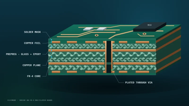
FR-4 is a laminate made from woven fibreglass cloth bound with an epoxy resin. The “FR” stands for flame retardant: the resin system is formulated to self-extinguish, and FR-4 boards are typically rated UL94 V-0. The “4” is simply its grade in the NEMA classification of laminate materials.
In a finished PCB, FR-4 forms the core and prepreg layers that sit between the copper. It gives the board its mechanical strength, insulates the copper layers from each other and sets much of the board's electrical behaviour.
It became the industry standard for good reasons:
- It is low cost and available from every board house
- It is strong, rigid and stable across normal operating temperatures
- It has good electrical insulation and reasonable dielectric performance
- It works for everything from simple two-layer boards to complex multilayer PCB design
That flexibility is also the trap. “FR-4” is a family of materials, not one material, and the differences between grades matter a lot for PCB reliability.
The FR-4 properties that actually matter
When you pick a laminate from a datasheet, five properties do most of the work. Exact values vary by manufacturer and grade, so always check the datasheet for the specific material your board house uses.
| Property | What it means | Why it matters for board life |
|---|---|---|
| Tg (glass transition temperature) | The temperature where the resin changes from rigid to soft and rubbery | Above Tg the board expands quickly and loses strength |
| Dk (dielectric constant) | How the material stores electrical energy, typically around 4 to 4.8 for FR-4 | Sets trace impedance and signal speed |
| Df (loss tangent) | How much signal energy the material absorbs as heat | Limits how well high-speed and RF signals survive |
| CTE (coefficient of thermal expansion) | How much the material grows as it heats, especially through its thickness (Z-axis) | Z-axis growth stretches and cracks via barrels |
| Moisture absorption | How much water the laminate takes up from the air | Trapped moisture turns to steam during soldering and causes delamination |
Of these, Tg and Z-axis CTE have the biggest effect on PCB lifespan. Dk and Df matter most for signal integrity on fast or RF designs.
Standard vs high Tg FR-4
Standard FR-4 typically has a Tg of around 130 to 140 °C. Mid-Tg grades sit around 150 °C, and high Tg FR-4 is generally 170 °C or above.
Standard FR-4 is fine for many consumer and office products. High Tg FR-4 is worth the small extra cost when:
- The board runs hot, for example near power stages, motor drivers or LEDs
- It sits in a sealed or outdoor enclosure that heats up in the sun
- It goes through lead-free reflow, which runs hotter than older leaded processes
- It is a thick multilayer PCB with many plated vias, where Z-axis expansion does the most damage
- The product needs a long service life, such as EV chargers, industrial controls or energy equipment
When FR-4 is not enough
FR-4's loss tangent becomes a problem as frequencies climb. For multi-gigabit links, RF front ends, radar or mmWave designs, low-loss or RF laminates often give better signal integrity. Many designs use a hybrid stack-up: low-loss material only on the layers that carry fast or RF signals, with FR-4 for the rest to keep cost down.
If you are working on HDI PCB design or rigid-flex PCB builds, the material choice also has to suit laser-drilled microvias and the flex layers, so it is worth settling early with your designer and board house.
What shortens the life of an FR-4 PCB
FR-4 boards rarely fail all at once. They wear out through a handful of slow mechanisms:
- Thermal cycling. Every heat-up and cool-down makes the laminate, copper and solder expand at different rates. Over thousands of cycles this fatigues solder joints and via barrels.
- Via cracking. The board grows more through its thickness than the copper plating in the vias. Thin plating or tall, narrow vias crack first, often as intermittent faults that are hard to trace.
- Moisture. FR-4 absorbs water from the air. During reflow it turns to steam and can blister or split the layers.
- Delamination. Layers separating, caused by moisture, too much heat or a resin that can't handle lead-free temperatures.
- CAF growth. Conductive anodic filament is a copper path that grows along the glass fibres between closely spaced vias under voltage and humidity, eventually causing a short.
- Overheating components. A hot regulator or MOSFET can push the local board temperature past its Tg even when the rest of the board is cool.
- Poor stack-up choices. An unbalanced copper distribution or asymmetric stack-up leads to warping, which stresses joints and makes assembly harder.
- Via cracking at the barrel corner, as the board grows faster than the copper
- Delamination where trapped moisture flashes to steam in reflow
- CAF growth along the glass between closely spaced vias
- Local overheating that pushes the board under a hot part past Tg
- Solder-joint fatigue under BGAs from thermal cycling
The good news is that almost all of these are decided at the design stage.
How to increase FR-4 PCB life
These are the design habits that make the biggest difference to PCB reliability in our experience.
1. Choose the right Tg
Look at the hottest point the board will reach in use, not the ambient temperature, and leave a comfortable margin below Tg. Check that the material also suits your reflow profile. If you are unsure, high Tg FR-4 is usually a cheap insurance policy.
2. Get the thermal design right
Good thermal management in PCB design keeps hot spots well below Tg:
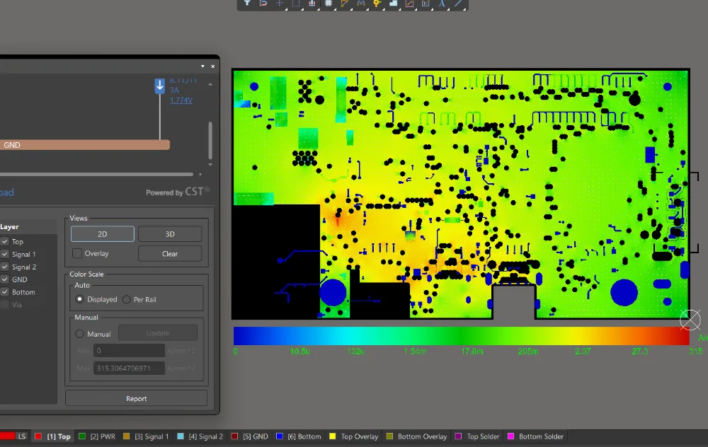
- Use copper pours and wider traces to spread heat from power parts
- Add thermal vias under exposed pads to carry heat to inner or bottom layers
- Keep hot components apart and away from sensitive parts and connectors
- Think about airflow and how the board sits in its enclosure
3. Use a balanced, symmetrical stack-up
Mirror the layer structure and copper weights about the centre of the board. Balance copper density between layers too. This keeps the board flat through reflow and in use, which protects BGAs and fine-pitch joints.
4. Design vias properly
Keep via aspect ratios within your fabricator's comfortable range, specify adequate plating thickness and give pads a healthy annular ring. On boards with high voltage between closely spaced vias, increase spacing to reduce CAF risk.
5. Protect boards in harsh environments
For humid, dusty or outdoor products, conformal coating adds a strong barrier against moisture and contamination. Plan for it in layout by keeping connectors and test points clear.
6. Store and bake boards correctly
Keep bare boards sealed with desiccant until assembly. Boards that have been exposed to humid air should be baked to drive out moisture before reflow, following your board house's guidance.
7. Review the design before you build
A proper DFM review and PCB design review catches stack-up, thermal and via problems while they are still free to fix. This is where most lifetime issues are won or lost.
When a design review saves money
A board spin costs more than the fabrication bill. There is the delay, the re-test, the re-certification for EMC compliance, and sometimes the cost of units already in the field. Finding a problem on screen is far cheaper than finding it in a returned product.
A good PCB design review looks at the board as a whole: material and stack-up choice, thermal paths, via design, signal integrity, power integrity, EMC risk and manufacturability. It works best when it is done by someone who didn't draw the board, because fresh eyes spot what the original designer has stopped seeing.
At Elecmore we carry out independent SI/PI/EMI/DFM reviews of existing boards, as well as full schematic and PCB layout services for new designs, including high-speed, HDI and rigid-flex work. We also design reliability-focused stack-ups from the start, so material choice and thermal performance are settled before routing begins.
20+ years of PCB life, planned before your board goes to fab
The habits above keep a board working for years. When a product has to last decades, in energy equipment, EV chargers, industrial controls, rail, defence or space hardware, we go further and plan its service life before a single board is fabricated.
Our Enhanced Lifetime & Reliability Analysis assesses the design component by component against how it will really be used: temperature, thermal cycling, humidity, vibration and duty cycle. We check the laminate's Tg and Z-axis CTE against the hottest point on the board, via-barrel and solder-joint fatigue under thermal cycling, and the derating of every part, then design out what would fail first while changes still cost nothing.
Before your board goes to fab, you get:
- Thermal-cycle and solder-joint reliability assessment where applicable
- Physics-of-failure assessment of critical areas such as vias, BGAs and power stages
- Identification of the components or mechanisms most likely to limit service life
- Predicted life and margin where the available component data supports a quantitative calculation
- Material, stack-up, coating and manufacturing recommendations to close any gaps
The result is a board designed for a 20+ year service life, with the evidence to back a 20-year warranty with confidence. Where the data cannot support a number, we tell you, and show what would.
Enhanced Lifetime & Reliability Analysis
Planning a product that has to last 20 years?
Conclusion: build boards that last
FR-4 is a reliable, cost-effective material when it is chosen and used with care. Pick the right Tg, manage heat, balance the stack-up, design vias properly and protect the board from moisture, and an FR-4 PCB will serve your product for years.
Elecmore is a UK electronics design consultancy supporting product companies with PCB design, embedded systems design and IoT product development, including Wi-Fi, BLE, LoRa and NB-IoT connectivity. We take designs from prototype through to production and board bring-up. If your team is stretched, we can also run a 2-week electronics overflow sprint on one defined board or subsystem.
If you'd like a second pair of eyes on an existing board, or want to talk through a new design, book a PCB design review or a short call with us, or email info@elecmore.com or ahzam@elecmore.co.uk.
Frequently asked questions
How long does an FR-4 PCB last?
There is no single number. Board life depends on operating temperature, thermal cycling, humidity and design quality. A well-designed board in a stable environment can last many years, while the same board running hot or in humid conditions will wear out much sooner.
When should I use high Tg FR-4 instead of standard FR-4?
Use high Tg FR-4 when the board runs hot, goes through lead-free reflow, has many layers and plated vias, or needs a long service life in harsh conditions. For most cool-running consumer boards, standard FR-4 is enough.
Can a PCB be designed to last 20 years or more?
Yes, where the application and the component data support it. Our Enhanced Lifetime & Reliability Analysis checks the laminate, vias, solder joints and every component against the real operating profile before fabrication, designs out what would fail first, and gives you the evidence to back a 20-year warranty.
Can you review a PCB design that is already finished?
Yes. An independent design review can be done on existing schematics and layout files before fabrication or before a redesign. If you are looking for PCB design services in the UK, Elecmore offers SI/PI/EMI/DFM reviews as a standalone service.
Work With Us
Want a second pair of eyes on your stack-up, thermal design or vias before you build?
Contact Elecmore:
info@elecmore.com
ahzam@elecmore.co.uk
Book a PCB design review